GEOMETRIC DIMENSIONING & TOLERANCING (GD&T) TRAINING
Communicating Design Intent with Precision and Clarity
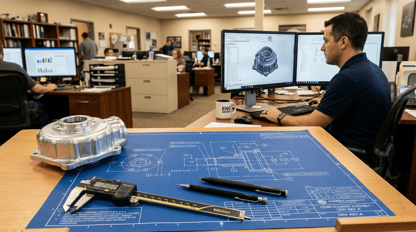
Understand and apply Geometric Dimensioning and Tolerancing (GD&T), the international symbolic language used on engineering drawings to define and communicate tolerances for form, orientation, location, profile, and runout.
Geometric Dimensioning and Tolerancing (GD&T) is a crucial system based on symbolic language (conforming to standards like ASME Y14.5) used on engineering drawings and CAD models to explicitly describe nominal geometry and its allowable variation. It ensures clarity in design intent, proper assembly fit, and functional interchangeability of parts.
Mastering GD&T allows engineers, designers, manufacturers, and inspectors to speak the same precise language, reducing ambiguity, preventing interpretation errors, and ensuring parts function as intended. It moves beyond traditional plus/minus tolerancing to control specific geometric characteristics critical to function.
Why Choose Tetrahedron for GD&T Training?
Tetrahedron's GD&T training is delivered by certified experts (e.g., ASME GDTP) with extensive practical experience in design, manufacturing, and inspection. We focus on explaining the 'why' behind the symbols and rules, using numerous drawing examples, physical part demonstrations, and interactive exercises based on the latest ASME Y14.5 standard. Our goal is to build true understanding and practical application skills, not just symbol recognition.
Ready to master the language of engineering drawings?
Enroll in our comprehensive GD&T training program.
Key GD&T Concepts & Symbols Covered

Our training covers the fundamental rules, symbols, and concepts of GD&T based on the ASME Y14.5 standard, including datums, feature control frames, geometric characteristics (Form, Orientation, Location, Profile, Runout), material condition modifiers (MMC, LMC, RFS), and practical application examples.
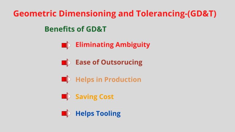
Key Benefits
Improved Communication & Clarity
Provides a universal, unambiguous language for defining design intent on drawings.
Ensured Functional Fit & Interchangeability
Guarantees that parts produced by different manufacturers or at different times will assemble and function correctly.
Optimized Manufacturing & Inspection
Allows for larger tolerances where possible (bonus tolerance) and clarifies inspection requirements.
Reduced Ambiguity & Interpretation Errors
Minimizes costly mistakes caused by misinterpreting traditional tolerance methods.
Lower Production & Inspection Costs
Clear definitions and potential for larger tolerances can reduce manufacturing and inspection expenses.
Facilitates Global Collaboration
GD&T standards (like ASME Y14.5) enable seamless collaboration across international teams and suppliers.
Who Should Attend This GD&T Training?
GD&T Training Course Outline (Based on ASME Y14.5)
- Introduction to GD&T: Purpose, History, Standards (ASME Y14.5)
- Fundamental GD&T Rules and Concepts
- The Feature Control Frame: Structure and Elements
- Datums: Datum Features, Datum Simulators, Datum Reference Frames (DRFs)
- Form Tolerances (Flatness, Straightness, Circularity, Cylindricity)
- Orientation Tolerances (Perpendicularity, Parallelism, Angularity)
- Location Tolerances (Position, Concentricity, Symmetry)
- Profile Tolerances (Profile of a Line, Profile of a Surface)
- Runout Tolerances (Circular Runout, Total Runout)
- Material Condition Modifiers (MMC, LMC, RFS) and Boundary Calculations
- Virtual Condition, Resultant Condition
- Applying GD&T to Drawings: Interpretation and Application Exercises
- Relationship between GD&T and Manufacturing/Inspection Processes
- Overview of Tolerance Stack-up Analysis (Introduction)
- Review of common symbols and drawing examples
Training Methodology
- Expert Instruction based on ASME Y14.5 Standard
- Clear Explanation of Symbols, Rules, and Concepts
- Numerous Drawing Interpretation Exercises
- Practical Application Examples
- Interactive Discussions and Q&A
- Physical Part Demonstrations (where applicable)
- Knowledge Checks and Assessments
Ensuring Design Precision with Industry Partners